 Slic3r Manual
 Slic3r Manual
This page will provide an overview of the available configuration settings in Slic3r. Every configuration option has a tooltip and it is recommended to read those tooltips.
The Print Settings tab provides the opportunity to change settings related to the actual print. Whereas the other tabs are changed rarely, the settings on this tab will be modified regularly, possibly for each model printed.
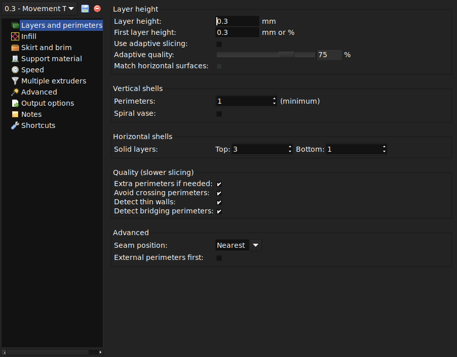
Print Settings: Layers and Perimeters
Layer height is the thickness of each layer, and it is the step along the vertical axis taken before extruding a new layer atop the previous one. There are several factors that influence how high each layer should be:
Desired resolution - Lower layer height should result in prints with less noticeable ribs or bands, as each layer is smaller. Aesthetics plays a role here, but also the type of model, for example, a mechanical part may not need such a high resolution finish, whereas a presentation piece may do so.
Print speed - Shorter layers will result in smoother prints but each print will take longer, simply because the extruder must trace the pattern more times. A later goal will be to strike a balance between layer height, the speed of the printer, and the quality of the resulting print.
Perimeters defines the minimum number of vertical shells (i.e. walls) a print will have. Unless the model requires single width walls it is generally recommended to have a minimum of two perimeters as this gives some insurance that if a section of the perimeter is not printed correctly then the second perimeter will help cover it.
The upper and lowermost layers that sandwich the model are filled with a Solid layers pattern. For the bottom layers the important factor to consider is how the surface will look should there be a mistake whilst laying down the first layer, and for this reason it is recommended to have at least two bottom layers.
A similar consideration is required for the top layers. Because the intermediate layers are likely to be filled with a pattern set less than 100% then the covering layers will have to bridge this pattern and this can require more than one pass to cover completely.
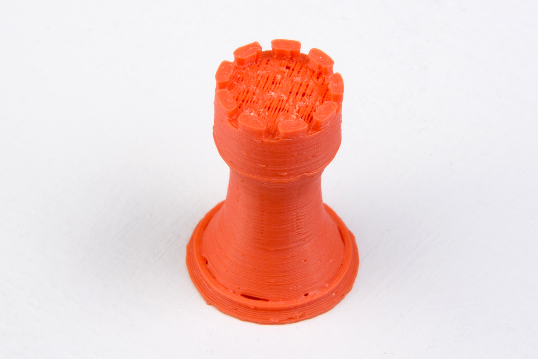
An example of insufficient top layers.
Another tip to consider: Setting the top solid layer to zero, and setting the infill also to zero, will result in a hollow receptacle, ideal for turning models into vases1 for example. Here manipulating the settings within Slic3r can be used to generate different kinds of prints, and not only be used to control surface accuracy.
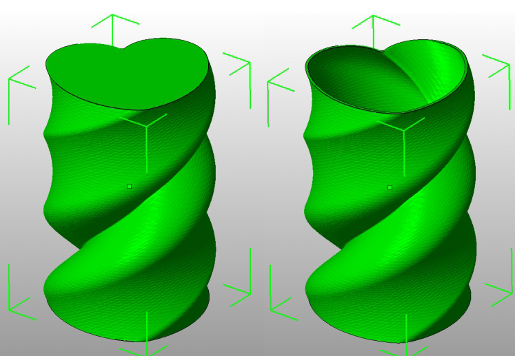
Creating a vase from a solid model.
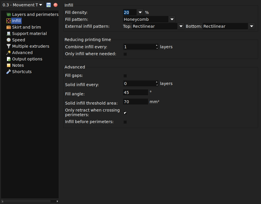
Print Settings: Infill
Fill density is from 0% to 100%. it makes no sense to 100% fill the model with plastic, this would be a waste of material and take a long time. Instead, most models can be filled with less material which is then sandwiched between layers filled at 100% (see Solid layers above).
A density value of 40% is enough to give almost all models good mechanical strength. A value of 20% is usually the minimum required to support flat ceilings.
Slic3r offers several fill patterns which will be discussed in more depth in section - Infill Choices. Choosing a Fill pattern will depend on the kind of model, the desired structural strength, print speed, and personal taste. The more exotic fill methods are usually too slow and unnecessarily complex for most use cases, and so most of the time the infill pattern is either rectilinear, line, or honeycomb. Honeycomb gives the most strength but is slower than both rectilinear or line.
There are several considerations when choosing an infill pattern: object strength, time and material, personal preference. It can be inferred that a more complex pattern will require more moves, and hence take more time and material.
Slic3r offers several infill patterns, four regular, and three more exotic flavours. The numbers given in brackets below each figure are a rough estimate of material used and time taken for a simple 20mm cube model2. Note that this is only indicative, as model complexity and other factors will affect time and material.
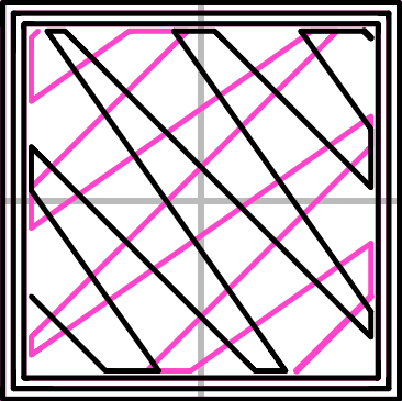
Infill pattern: Line (344.51mm / 5m:20s)
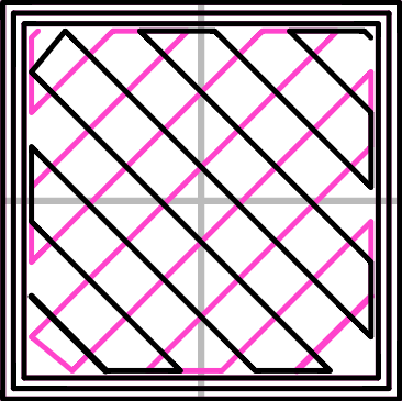
Infill pattern: Rectilinear (350.57mm / 5m:23s)
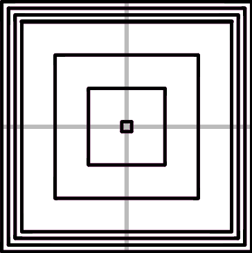
Infill pattern: Concentric (351.80mm / 5m:30s)
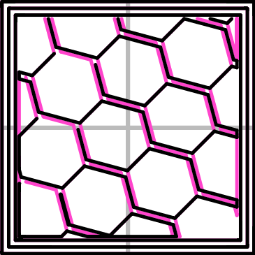
Infill pattern: Honeycomb (362.73mm / 5m:39s)
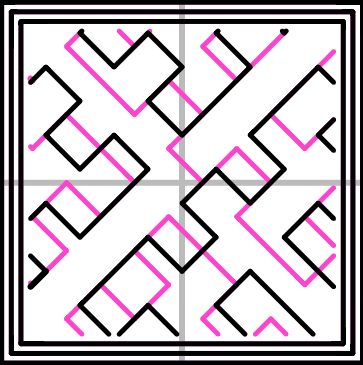
Infill pattern: Hilbert Curve (332.82mm / 5m:28s)
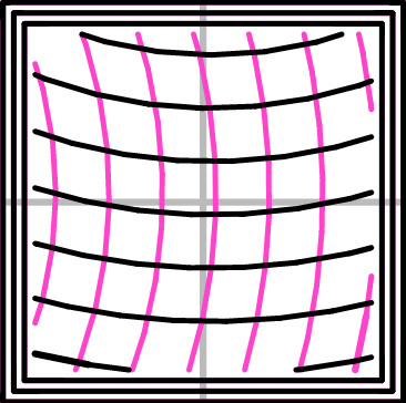
Infill pattern: Archimedean Chords (333.66mm / 5m:27s)
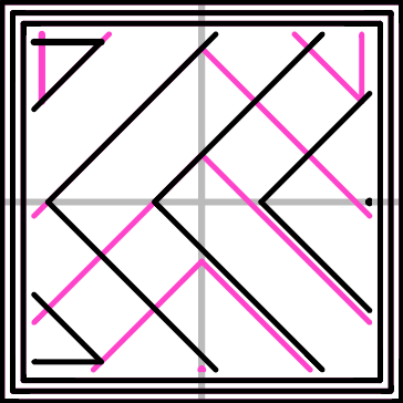
Infill pattern: Octagram Spiral (318.63mm / 5m:15s)
Certain model types are more suited for a particular pattern, for example organic versus mechanical types. Figure shows how a honeycomb fill may suit this mechanical part better because each hexagon bonds with the same underlying pattern each layer, forming a strong vertical structure.
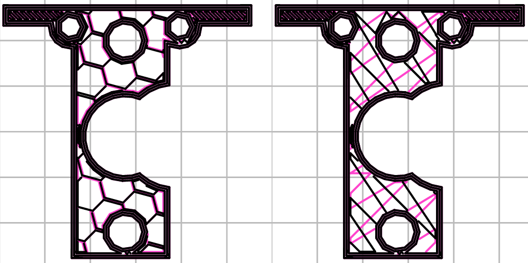
Infill pattern comparison in a complex object. Left to Right: honeycomb, line
Most models require only a low density infill, as providing more than, say, 50% will produce a very tightly packed model which uses more material than required. For this reason a common range of patterns is between 10% and 30%, however the requirements of the model will determine which density is best. Figure shows how the patterns change as the density increases.
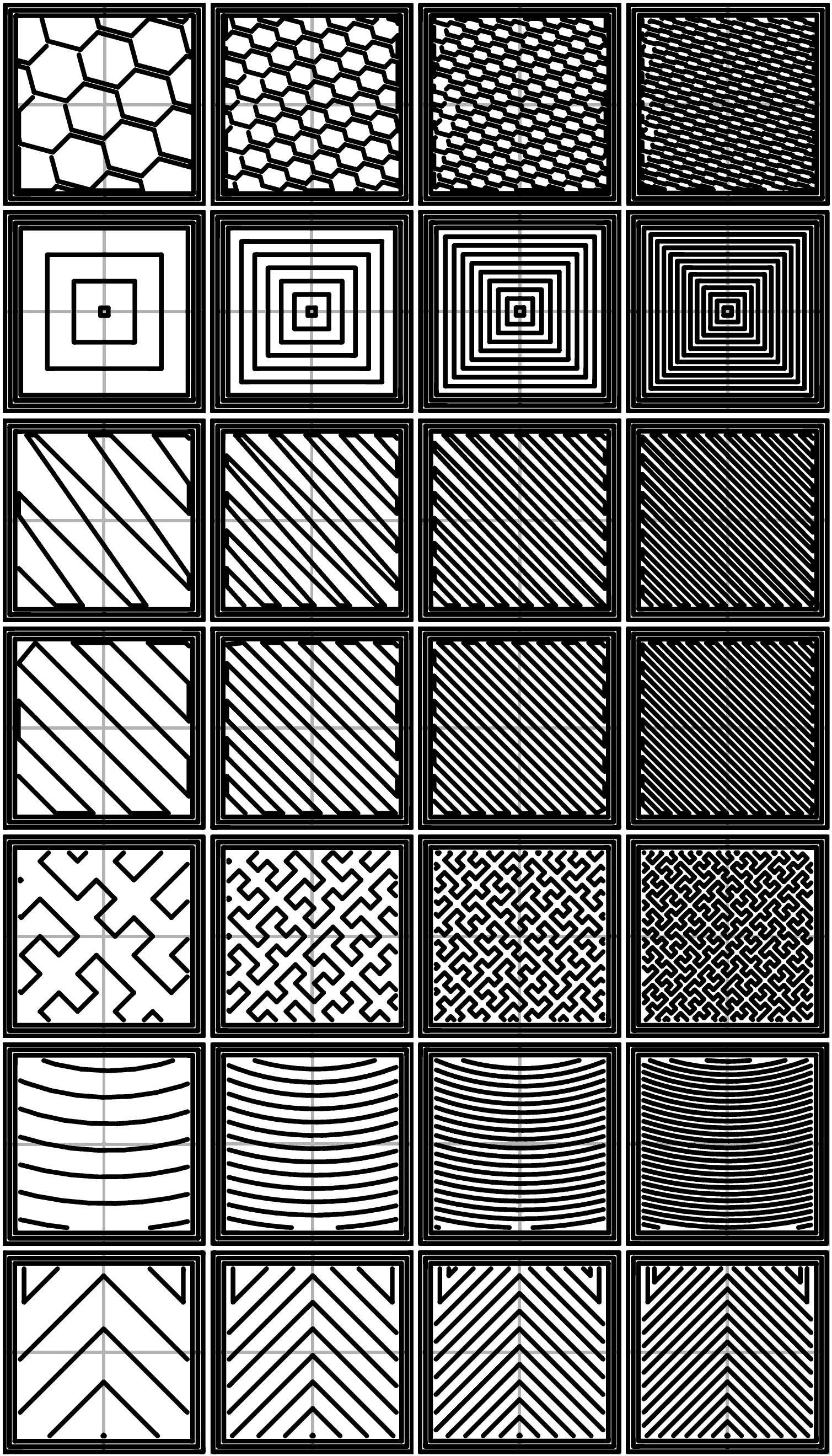
Infill patterns at varying densities. Left to Right: 20%,40%,60%,80%. Top to Bottom: Honeycomb, Concentric, Line, Rectilinear, Hilbert Curve, Archimedean Chords, Octagram Spiral
There are several 3D patterns available for 3d infill as well.
Cubic infill is a 3D cube pattern with each cube stacked on corners. 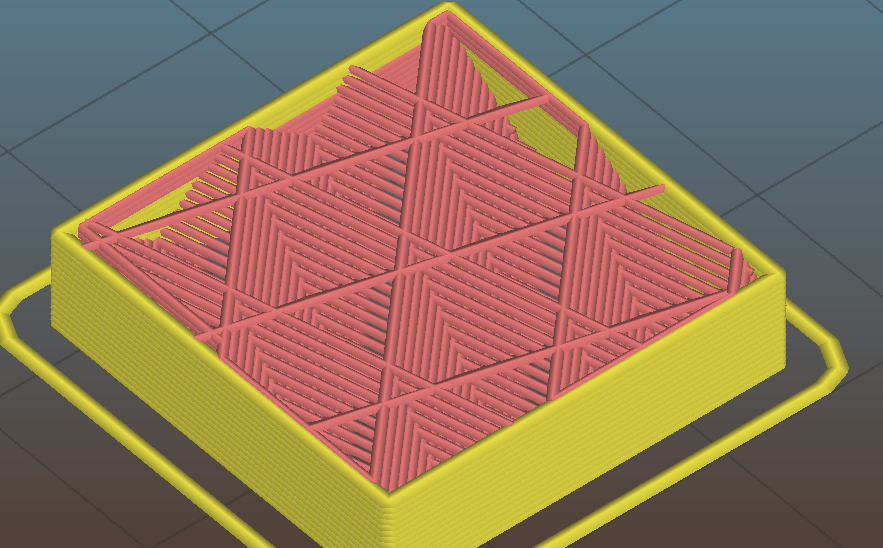
3D Honeycomb is a true honeycomb pattern. 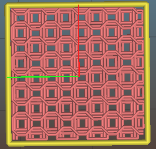
Slic3r contains several advanced infill settings which can help produce better extrusions.
Infill every n layers - Will produce sparse vertical infill by skipping a set number of layers. This can be used to speed up print times where the missing infill is acceptable.
Only infill where needed - Slic3r will analyse the model and choose where infill is required in order to support internal ceilings and overhangs. Useful for reducing time and materials.
Solid infill every n layers - Forces a solid fill pattern on the specified layers. Zero will disable this option.
Fill angle - By default the infill pattern runs at 45° to the model to provide the best adhesion to wall structures. Infill extrusions that run adjacent to perimeters are liable to de-laminate under stress. Some models may benefit from rotating the fill angle to ensure the optimal direction of the extrusion.
Solid infill threshold area - Small areas within the model are usually best off being filled completely to provide structural integrity. This will however take more time and material, and can result in parts being unnecessarily solid. Adjust this option to balance these needs.
Only retract when crossing perimeters - Retracting, to prevent ooze, is unnecessary if the extruder remains within the boundaries of the model. Care should be taken if the print material oozes excessively, as not retracting may result in enough material loss to affect the quality of the subsequent extrusion. However, most modern printers and materials rarely suffer from such extreme ooze problems.
Infill before perimeters - Reverses the order in which the layer is printed. Usually the perimeter is laid down initially, followed by the infill, and this is usually the preferable as the perimeter acts as a wall containing the infill.
Print Settings: Support Material
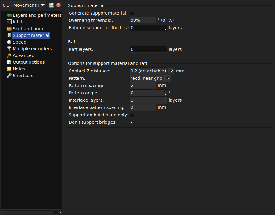
Printing a model from the bottom up, as with FDM, means that any significant overhangs will be printed in the air, and most likely droop or not print correctly. Choosing support material (Generate support material) will add additional structures around the model which will build up to then support the overhanging part. The Pattern spacing option determines how dense the support material is printed.
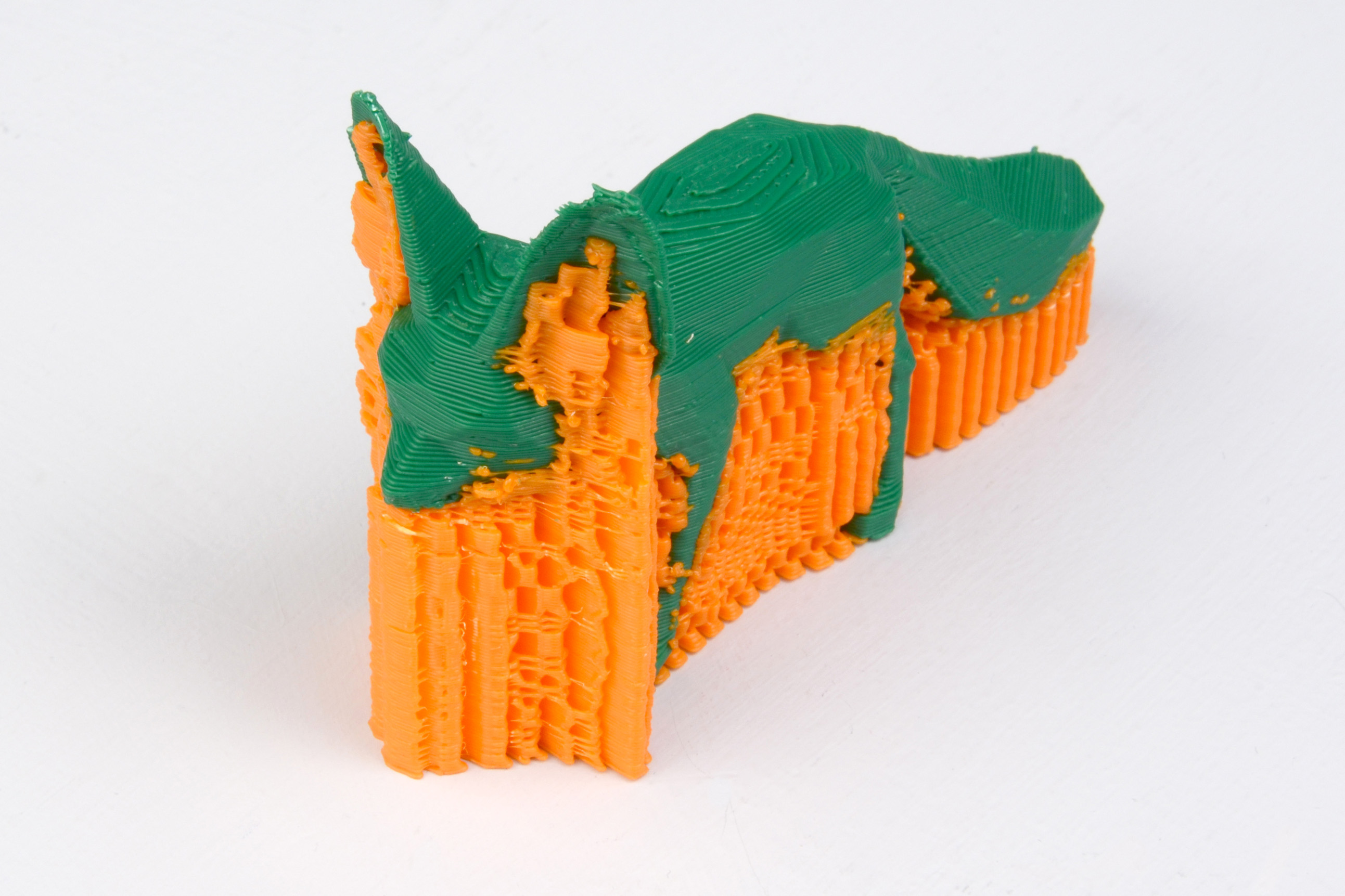
An example of an object printed with support material.
Tip: It is sometimes worth considering altering the orientation of the model in order to possibly reduce overhangs.
Raft layers will add additional layers underneath the model and stems from the early days of 3D printing. The following use cases are appropriate for raft usage: - Print is using a material that usually requires a heated bed to not warp and there is no heated bed. - The bed is not very flat. A raft then absobes the variance in Z for the first layer. - The part has a very small contact area with the bed. Usually a wide brim is a better solution.
Otherwise, rafts are generally not recommended. The raft also requires post-processing to remove it.
Rafts are classified as support material, while the top layer of the raft (the one directly underneath the model) is interface material and as such uses those settings.
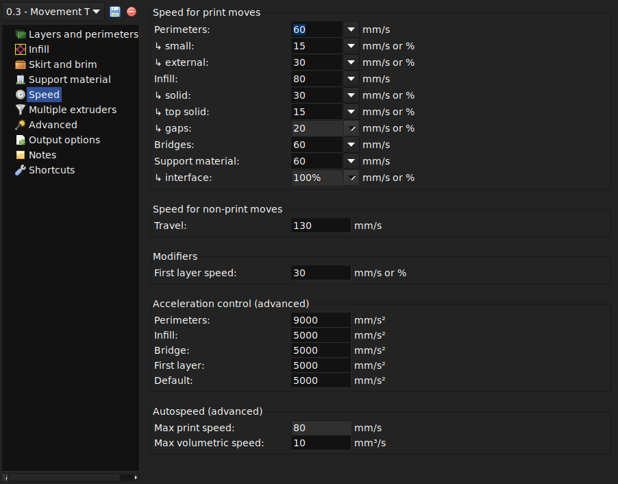
Print Settings: Speed
There are two general categories of speeds: print moves and non-print moves.
For print moves, each type of printing move can be configured to have a different speed, either in absolute terms (mm/s) or as a percentage of the more general move.
Perimeters - The outline of the model may benefit from being printed slightly slower so that the outside skin of the print has fewer blemishes.
Small perimeters - Meant for holes, islands and fine details, a slower speed here is recommended.
External perimeters - A slightly slower value may ensure cleaner surfaces.
Infill - As the infill is hidden this can be extruded a little faster. Take care though not to go too fast as higher speeds results in thinner extrusions, and this may affect how the extrusions bond.
Solid infill - The bottom of the model, and any additional solid layers is usually slightly slower than infill but faster than perimeters.
Top solid infill - Allow time for the extrusion to cleanly cover the previous top layers and result in a tidy top surface. the last few layers should have bridged the infill structure nicely, preparing the way for a neat finish.
Gap fill - Filling in small gaps results in the extruder quickly oscillating and the resulting shaking and resonance could have a detrimental affect on the printer. A smaller value here can guard against this. Gap fill may be disabled in the 'Infill' settings.
Bridges - Having the extrusion span distances depends on the material and cooling. Going too slow will result in sagging, too fast will result in broken strands. Experimentation is the key here, but generally bridging runs slower than perimeters.
Support material - These are used if any support material (including rafts and brims) is included in the print. Usually it is printed as thick as possible, so a high speed may cause flow rate issues.
The one non-print move is travel moves.
Travel - The jump between the end of one extrusion and the next should usually be performed as quickly as the printer will allow in order to minimise any mess caused by material oozing from the nozzle.All print moves on the first layer may be changed with the provided modifier, either as a flat percentage or a fixed speed.
If your printer firmware supports acceleration control, you can enter in values here to change acceleration for the different general print moves.
If you set any print speed value to auto, configure the fastest printing speed you want for this print and Slic3r will choose speeds itself in an attempt to maintain constant pressure in the extruder.
Setting Max volumetric speed will tell Slic3r to not exceed the given flow rate for any printing moves. Set it to 0 to disable this feature.
There are 2 experimental methods to derive the max extrusion rate:
Once the printer is reliably producing good quality prints it may be desirable to increase the speed. Doing this provides several benefits, the most obvious of which is that the results are produced quicker, but also faster print times can be utilised in producing more layers, i.e. lower layer height, thus improving perceived print quality. An additional benefit is that a faster travel movement, between extrusions, can reduce the effects of oozing.
The best approach is to increment the various speed parameters in small steps and observe the effect each change has on print quality. Travel speed is a safe starting point, and it is not unrealistic to attain speeds of up to 250mm/s (if your printer can handle it). Adjusting the speed of perimeters, infill is available in simple mode, and the general rule is to have the perimeter go a little slower than the infill in order to reduce possible blemishes on the surface (infill can be faster because slight gaps will not matter as much).
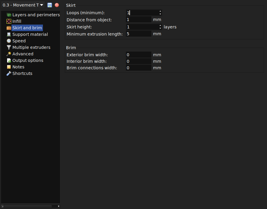
Print Settings: Skirt and Brim
Brim width is used to add more perimeters to the first layer, as a base flange, in order to provide more surface area for the print to stick to the bed with in order to reduce warping (see §). The brim is then cut away once the print is finished and removed from the bed. Interior brim width adds a brim inside of holes in the print.
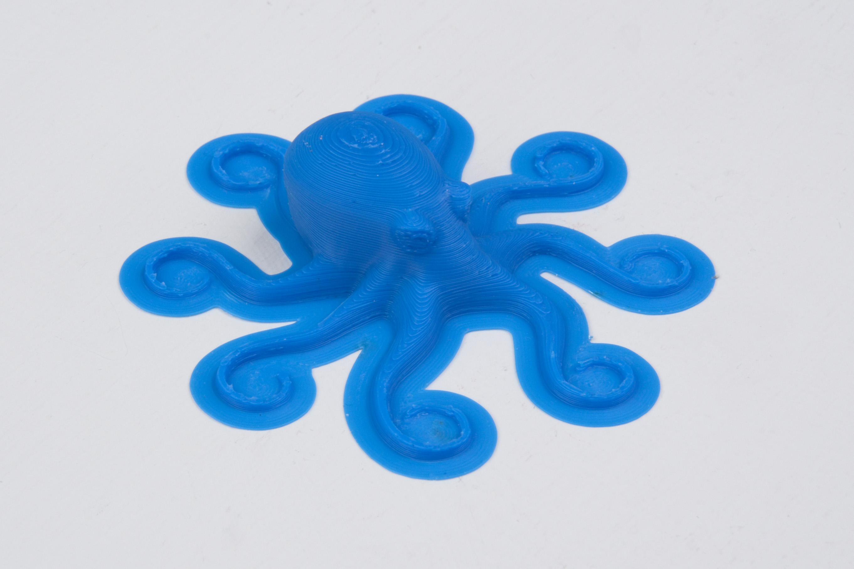
An example of brim.
Brim ears will print the brim only around sharp corners. The Brim ears Maximum Angle setting allow to choose the sharpness of the angle. An angle below 90° won't draw a grim ear around each corner of a cube, but an angle of 91° will.
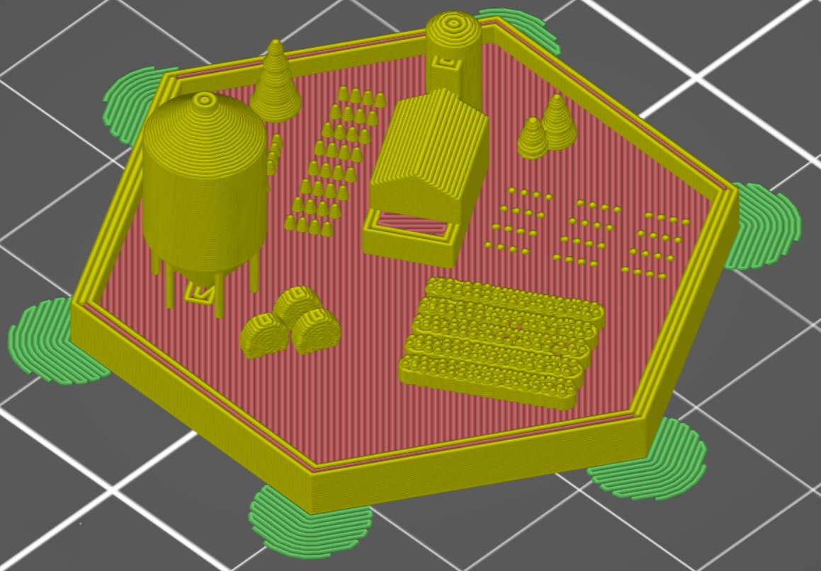
An example of brim ears. (model made by b1sh0p)
The Skirt setting adds an extrusion a short distance away from the perimeter of the object. This can ensure that the material is flowing smoothly from the extruder before it starts on the model proper.
Loops - How many circuits should be completed before starting on the model. One loop is usually sufficient.
Distance from object - The millimeters between the object and the skirt. The default of 6mm is usually sufficient.
Skirt height - The number of layers to lay down a skirt for. For ensuring the material is flowing smoothly, one layer is sufficient, however the skirt function can also be used to build walls around the object in case it should be protected from draughts.
Minimum extrusion length - Dictates a minimum number of millimeters that the skirt should be, should the loop around the object not be enough.
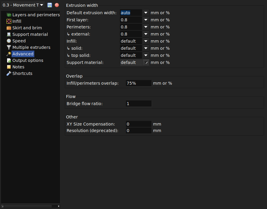
Extrusion widths options.
One reason for modifying the extrusion width has already been discussed: increasing first layer extrusion width in order to improve bed adhesion (see p.). There are some further cases where it may be beneficial to modify extrusion widths.
Perimeter - A lower value will produce thinner extrusions which in turn will produce more accurate surfaces.
Infill and Solid Infill - A thicker extrusion for infill will produce faster prints and stronger parts.
Top infill - A thinner extrusion will improve surface finish and ensure corners are tightly filled.
Support material - As with the infill options, a thicker extrusion will speed up print time.
It is important to remember that if the extrusion width is expressed as a percentage then this is computed from the Layer height property, and not the Default extrusion width setting.
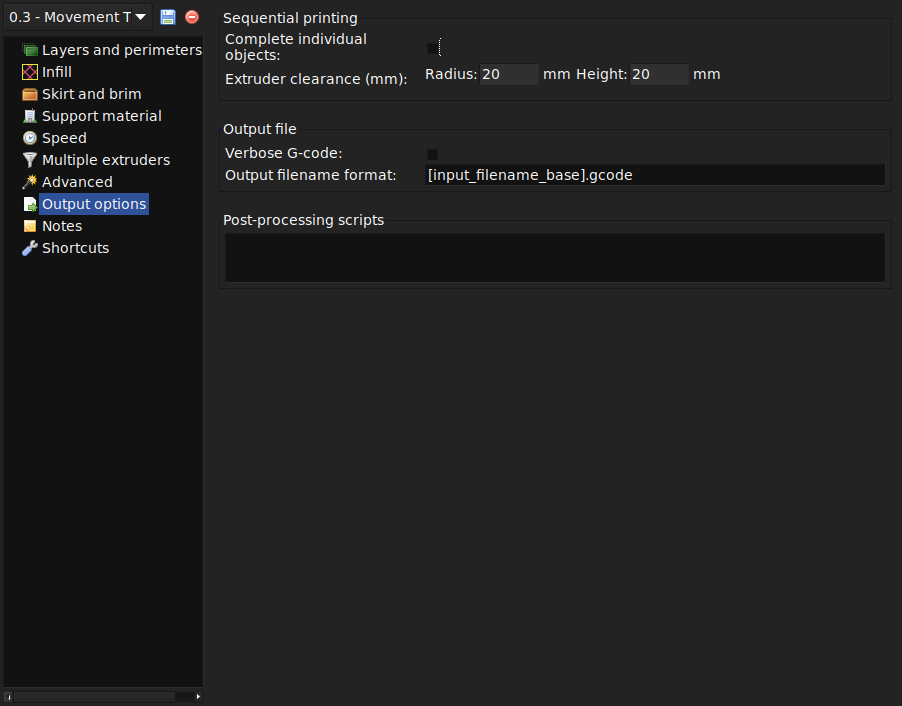
Print Settings: Output Options
This feature allows to compose a plate of objects but have the printer complete each one individually before going back to Z = 0 and starting with the next one. See the section about Sequential Printing in the Advanced Topics chapter.
Verbose G-Code turns on extra comments to document the types of print moves in the output G-Code. Very useful for debugging.Output filename format describes the general format for how Slic3r automatically names export G-Code files. All of the usual variables are supported here.Post-processing scripts are a powerful way to modify output G-Code after the slicing process has completed and as such have their own section in Advanced Topics.
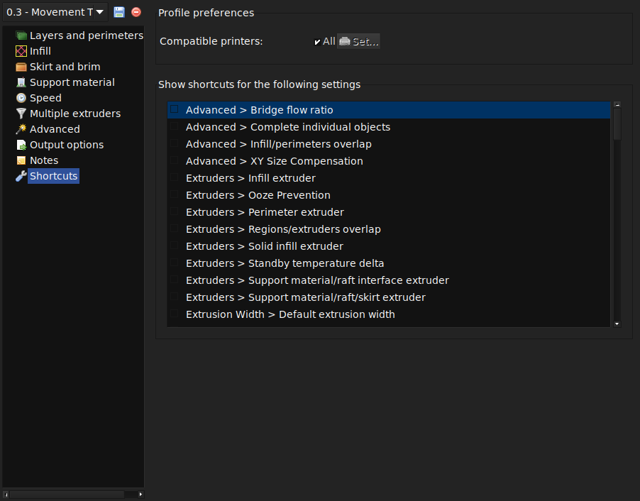
Print Settings: Shortcuts
For configuration options that you modify often, Slic3r provides a way to pre-register those options so that they are configurable from the plater. Simply check a box for each.
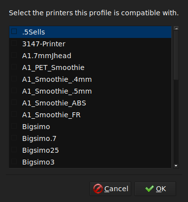
Print Settings: Compatible Printers
Use this dialog to mark which printer profile(s) this print profile can be used with. The default is to "All" printer profiles.