 Slic3r Manual
 Slic3r Manual
A printer with more than one extruder can be used in different ways. If you have a multi-part model, that defines distinct regions, you can assign each one of them to an extruder. If you have a single part model, you can assign different roles to each extruder: for example, you can infill using a larger nozzle or you can build support material with soluble filament.
In the Printer Settings tab there is an Extruders option, under Capabilities, which allows the number of extruders to be defined. Incrementing this value will dynamically add another extruder definition to the left-hand pane.
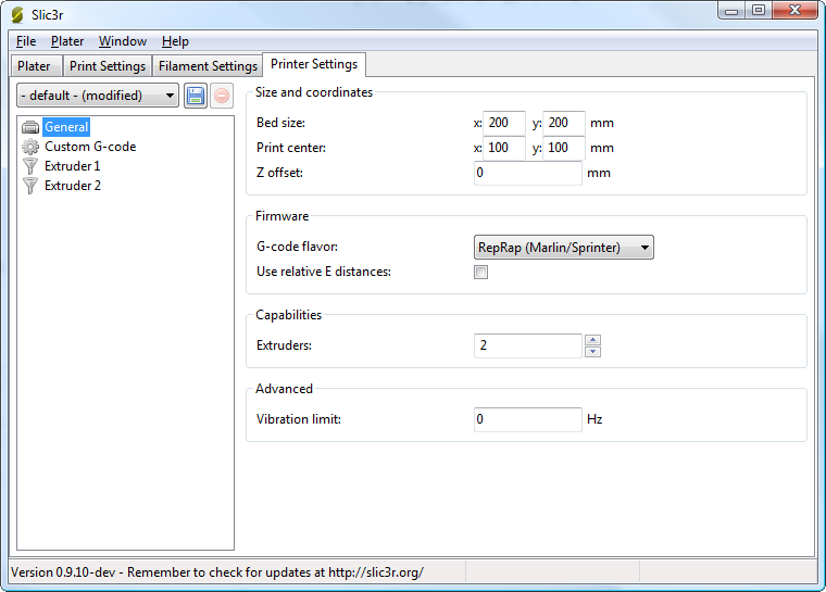
Multiple extruder options - Printer Settings Tab (General). Note the two extruders defined in the left-hand pane.
Each extruder can be configured as usual, however there are additional settings which must be set which are particular to multi-extruder setups.

Multiple extruder options - Printer Settings Tab (Extruder).
The Extruder offset is to be used should the firmware not handle the displacement of each additional nozzle. Your firmware documentation should tell you if this is the case. Each additional extruder is given an offset in relation to the first one (which usually has 0,0 offset). If the firmware does handle the displacements then all offsets can remain at 0,0.
Because the secondary extruder will be dormant whilst the first is working, and vice-versa, it is important that the material is sufficiently retracted to stop oozing. As with the regular retraction settings the Length options is measured from the raw filament entering the extruder.
The Custom G-code section of the Printer Settings tab has an option for inserting G-code between tool changes. As with all custom G-code sections, placeholder variables can be used to reference Slic3r settings. This includes the [previous_extruder] and [next_extruder] variables.

Multiple extruder options - Tool change G-code.
When a printer profile with multiple extruders has been selected the Plater tab allows the selection of a different filament for each extruder.
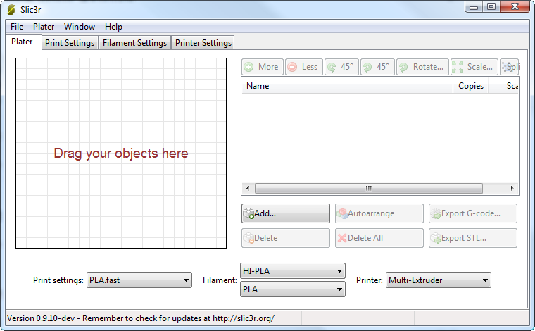
Plater with multiple filament options.
For single material prints, where the secondary extruder is to be tasked with a particular extrusion, the Multiple Extruders section of the Print Settings tab gives the ability to assign an extruder to each extrusion type.
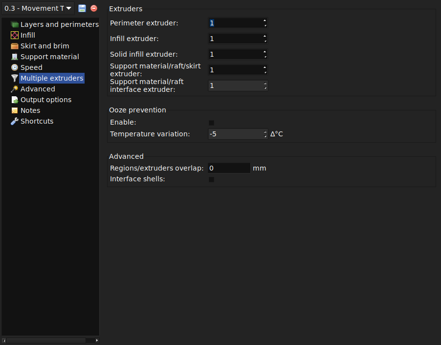
Multiple extruder options - Print Settings Tab.
If a multi-material AMF file already exists, because the CAD program can export such a format, then this can be loaded into Slic3r in the usual way. The mapping between object materials and extruders is sequential, i.e. the first material is assigned to the first extruder, etc.
Slic3r has the feature to combine multiple STL files into a multi-material AMF file.
Split the original design into the separate parts within the CAD program, and export each part as STL.
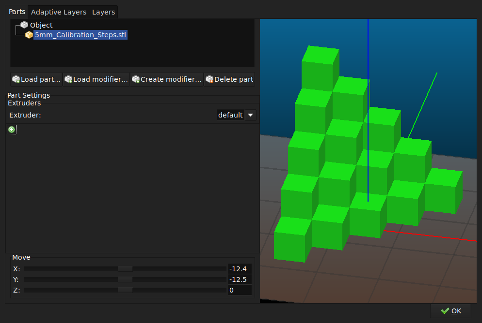
Click "OK" and right-click the combined part again and select "Export to AMF".
Once generated the file can be loaded and printed as described above.